Monday, 29 February 2016

LED driven circuit

MP3302 MP3302 is a boost converter IC specifically designed for LED drive applications. The MP3302 can drive 27 LEDs (9 strings of 3 w... thumbnail 1 summary

MP3302
MP3302 is a boost converter IC specifically
designed for LED drive applications. The
MP3302 can drive 27 LEDs (9 strings of 3
white LEDs in series) from a Lithium ion
battery. The IC has internal power MOSFETs
for driving the LEDs and has an efficiency of
88%. Switching frequency is 1.3MHz and the
internal current limit is 1.33A. Other features
of the MP3302 are open load shut down,
thermal shut down, under voltage lock out
etc. Applications of Mp3302 are LED back
lights, LED based lighting gadgets etc.
Functional block diagram of the MP3302 is
shown below (Fig1).
MP3302 functional block diagram
The IC uses a constant current , peak current
mode step up regulator scheme for regulating
the current through the LEDs. At
the beginning of each oscillator cycle, the
control circuitry switches the power MOSFET
ON. For preventing sub harmonic oscillation,
a stabilizing ramp signal is added to the
current sense amplifiers output and the
resultant signal is given to the non inverting
input of the PWM comparator. When this
resultant voltage  is equal to the voltage at
the PWM comparator’s inverting input
(output voltage of the error amplifier), the
power MOSFET is switched OFF. The error
amplifier’s output is the difference between
the feedback voltage and the reference
voltage. When the output voltage drops, the
feedback voltage also drops and this in
increases the output of the error amplifier.
This in turn increases duty cycle of the power
MOSFET drive signal produced by the control
circuitry which increase the duty cycle of the
power MOSFET, it conducts more current and
the output voltage is regulated. Circuit
diagram of a 27 LED driver circuit using
MP3302 is shown below (Fig 2).
MP3302 LED driver circuit diagram.
MP3302 LED driver IC circuit
C1 is the input bypass capacitor and C2 is
the output bypass capacitor. Resistor R1 is
the feedback resistor and it controls the LED
current. The governing equation is: LED
current = 195mV /R1 . Resistors tagged R are
the current limiting resistors for the
corresponding strings and they can be used
for limiting the maximum brightness of the
LEDs. A voltage level less than 0.4V to the EN
pin will shut down the IC and a voltage level
greater than 0.7V will enable the IC. Dimming
of the LEDs can be achieved by providing a
PWM signal in the range of 200Hz to 1KHz to
the EN pin. The absolute minimum amplitude
of the PWM signal is 1.5V. The built in open
load protection circuit will shut down the IC
when ever the output voltage goes above
38V. The IC will remain in the shut down
mode until the power supply is re switched.

Sunday, 3 January 2016

Test Transistor using Multimeter

By diode testing mode Set your meter to the continuity / diode "bleep" test. Connect the red meter lead to the base of the t... thumbnail 1 summary

By diode testing mode

Set your meter to the continuity / diode "bleep" test. Connect the red meter lead to the base of the transistor. Connect the black meter lead to the emitter. A good NPN transistor will read a junction drop voltage of between 0.45v and 0.9v. A good PNP transistor will read "OL". Leave the red meter lead on the base and move the black lead to the collector. The reading should be the same as the previous test. Reverse the meter leads in your hands and repeat the test.  Now connect the black meter lead to the base of the transistor. Connect the red meter lead to the emitter. A good PNP transistor will read a junction drop voltage of between 0.45v and 0.9v. A good NPN transistor will read "OL". Leave the black meter lead on the base and move the red lead to the collector. The reading should be the same as the previous test.  Finally place one meter lead on the collector, the other on the emitter. The meter should read "OL". Reverse your meter leads. The meter should read "OL". This is the same for both NPN and PNP transistors.  With the transistors on a pcb in circuit, you may not get an accurate reading, as other things in the circuit may affect it, so if you think a transistor is suspect from the readings you have got, remove it from the pcb and test it out of circuit, repeating the above procedure.  OL = Open Line

Test Diode and Zener diode using Multimeter

By resistance checking method   Multimeter wires connected across the leads and measure the resistance. In forward bias the resistance... thumbnail 1 summary

By resistance checking method 

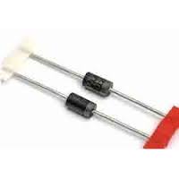
 Multimeter wires connected across the leads and measure the resistance. In forward bias the resistance is low and in reverse bias condition resistance is high. If the diode shows almost zero resistance,the diode is shorted and if the resistance is very high, the diode is open.  By diode testing mode  Fix multimeter to diode testing mode.And measure diode drop across it. If it shows 0.3 or 0.5-0.7 in forward bias condition the diode is normal.  


 In the case of zener diode the reading will be same for both forward and reverse bias condition. Because zener diode conducts in both directions.


Test Resistor using Multimeter

Using Resistsnce testing method Set multimeter to resistance checking.Resistor has no polarity. Check the resistance by connecting +... thumbnail 1 summary

Using Resistsnce testing method

Set multimeter to resistance checking.Resistor has no polarity. Check the resistance by connecting +ve end of multimeter to one end of resistor and -ve wire to other end. Also calculate the resistance of resistor by using color code.Compare both reading and replace resistor if the readings are different.  Checking open circuited resistors  If a resistor is reading a very high resistance, above its rated value, it is open. It is defective and, thus, should be replaced.  Checking shorted resistors  Shorted means zero resistance.If multimeter reading is zero or very low,the resistor is shorted.  Another method to check short by circuit continuity test in diode mode


Test Capacitor using Multimeter

Test a Capacitor with an Ohmmeter of a Multimeter   A very good test you can do is to check a capacitor with your multimeter set on th... thumbnail 1 summary

Test a Capacitor with an Ohmmeter of a Multimeter  

A very good test you can do is to check a capacitor with your multimeter set on the ohmmeter setting. By taking the capacitor's resistance, we can determine whether the capacitor is good or bad. To do this test, We take the ohmmeter and place the probes across the leads of the capacitor. The orientation doesn't matter, because resistance isn't polarized.  If we read a very low resistance (near 0Ω) across the capacitor, we know the capacitor is defective. It is reading as if there is a short across it. If we read a very high resistance across the capacitor (several MΩ), this is a sign that the capacitor likely is defective as well. It is reading as if there is an open across the capacitor. A normal capacitor would have a resistance reading up somewhere in between these 2 extremes, say, anywhere in the tens of thousands or hundreds of thousand of ohms. But not 0Ω or several MΩ. This is a simple but effective method for finding out if a capacitor is defective or not. 


Test a Capacitor with a Multimeter in the Capacitance Setting  

Another check you can do is check the capacitance of the capacitor with a multimeter, if you have a capacitance meter on your multimeter. All you have to do is read the capacitance that is on the exterior of the capacitor and take the multimeter probes and place them on the leads of the capacitor. Polarity doesn't matter. This is the same as the how the setup is for the first illustration, only now the multimeter is set to the capacitance setting. You should read a value near the capacitance rating of the capacitor. Due to tolerance and the fact that (specifically, electrolytic capacitors) may dry up, you may read a little less in value than the capacitance of the rating. This is fine. If it is a little lower, it is still a good capacitor. However, if you read a significantly lower capacitance or none at all, this is a sure sign that the capacitor is defective and needs to be replaced. Checking the capacitance of a capacitor is a great test for determining whether a capacitor is good or not.  

Test a Capacitor with a Voltmeter  

Another test you can do to check if a capacitor is good or not is a voltage test. Afterall, capacitors are storage devices. They store a potential difference of charges across their plate, which are voltages. The anode has a positive voltage and the cathode has a negative voltage. A test that you can do is to see if a capacitor is working as normal is to charge it up with a voltage and then read the voltage across the terminals. If it reads the voltage that you charged it to, then the capacitor is doing its job and can retain voltage across its terminals. If it is not charging up and reading voltage, this is a sign the capacitor is defective.